

Installation#
Mounting#
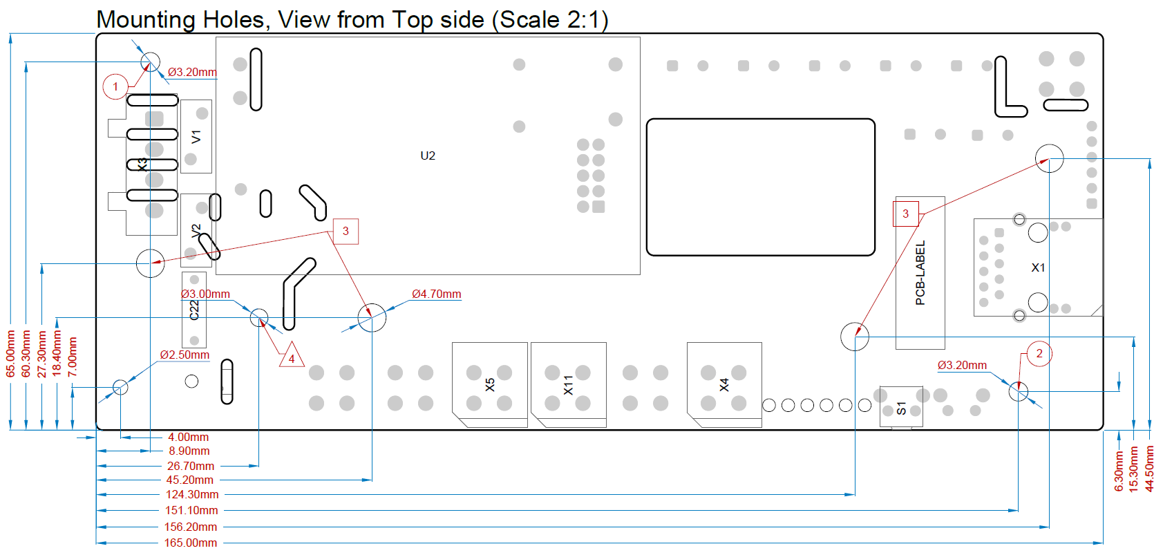
(1) Main Mounting Hole: Mechanical mounting point only; no electrical connection.
(2) Functional Earth (Ethernet): Electrical connection using a metal fastener. Required when a DCF receiver is used.
(3) Standoffs: Support the PCB at multiple points to prevent flexing when cable terminals are accessed.
(4) Function Earth (EMC / Chassis): Electrical connection to the local chassis ground using a metal fastener.
Class II Compliance: The product is designed as a Class II (double-insulated) device and does not rely on a protective earth connection for electrical safety.
Purpose: This connection is utilized purely as a Function Earth (FE) path for internal EMC suppression capacitors (Y-capacitors). Connecting it to an earthed chassis or enclosure does not affect the safety class of the device but is recommended for optimal electromagnetic compatibility.
Attention
The device must only be installed by a skilled person, such as a qualified electrician, who is familiar with the relevant regulations.
Warning
This equipment is not suitable for use in locations where children are likely to be present.
Note
The device must only be installed in a fire enclosure with protection against contact, dirt and water.
1
Disconnect all power sources - including the illumination switching input - before handling the PCB. Additionally, the NCC V2 VB may remain energized even after all external power sources are disconnected. After shutting down the device, wait at least one hour before handling it.
Interfaces and Variants#
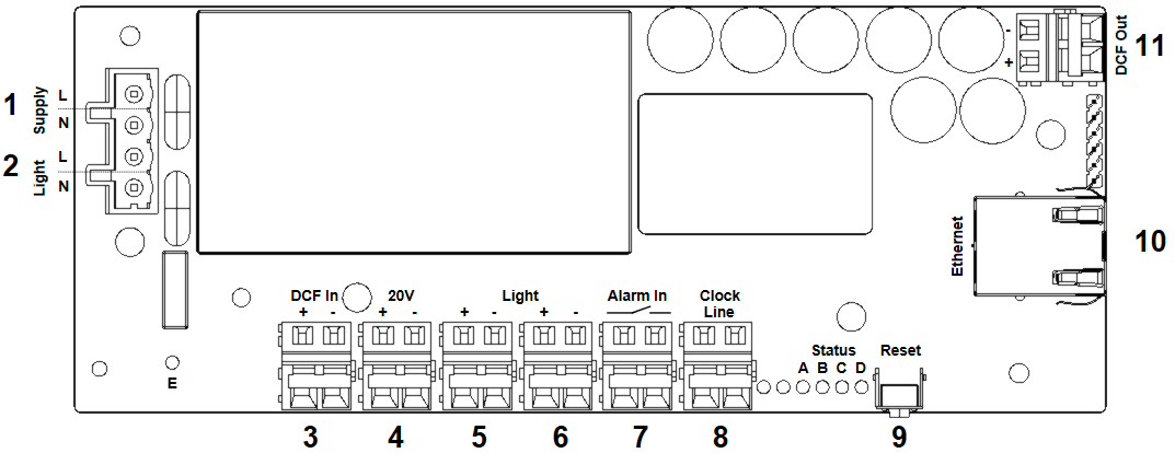
Three product variants are available, differing in feature set and interface availability. The following table summarizes these differences and the associated connections. Refer to the subsequent sections for detailed descriptions.
Label |
Name |
NCC V2 |
NCC V2 AC |
NCC V2 VB |
|---|---|---|---|---|
Ordering Information |
||||
- |
Ordering Number |
138422 |
138423 |
138424 |
- |
Spring Terminal Included |
✗ |
✓ |
✓ |
Power Supply |
||||
10 |
PoE / PoE+ |
✓ |
✓ |
✓ |
1 |
Mains |
✗ |
✓ |
✓ |
- |
Backup Supply |
✗ |
✗ |
✓ |
Indicators / Controls |
||||
9 |
Reset Button |
✓ |
✓ |
✓ |
A-D |
Status LEDs |
✓ |
✓ |
✓ |
Inputs and Outputs |
||||
10 |
Ethernet |
✓ |
✓ |
✓ |
8 |
Clock Line |
✓ |
✓ |
✓ |
5-6 |
Illumination |
✓ |
✓ |
✓ |
7 |
Alarm Input |
✗ |
✗ |
✓ |
2 |
LED Switching Input |
✗ |
✓ |
✓ |
3, 4 |
DCF Input |
✗ |
✗ |
✗ |
11 |
DCF Output |
✗ |
✗ |
✗ |
Mains#
Mains voltage connections are made using a 4-pole pluggable spring-clamp terminal block (WAGO 721 series). The LED switching input may be left unconnected if this function is not required. The maximum permissible conductor cross-section is 2.5 mm², and the insulation must be stripped to a length of 9-10 mm. All phase and neutral conductors shall be secured near the terminal block using cable ties.
Label |
Connection Type |
Nominal Voltage |
Voltage Tolerance |
Power Rating |
Length |
Description |
|---|---|---|---|---|---|---|
1 |
Terminal Block |
100-240 VAC |
+/- 10% |
30 W |
N/A |
Mains supply input that powers the device. |
2 |
Terminal Block |
100-240 VAC |
+/- 10% |
0.5 W |
N/A |
Switching input that can turn the LED illumination on an off. |
Warning
The external electrical installation must include an appropriate fuse and an all-pole mains switch for all mains connections.
Warning
Only use the original terminal block. We accept no responsibility for any damage to persons or property resulting from the use of plugs other than those provided, or from faulty or unsafe wiring.
Warning
Avoid stripping wires in a way that could lead to contact with other components. Make sure to attach strain reliefs to relieve the connection points of cables and lines from mechanical stress.
Attention
The power supply connection to the clock must be installed by a skilled person. National regulations must be followed.
Attention
Make sure all wires are disconnected from live voltage before handling them.
Warning
Power supply units may fail permanently if operated outside of the nominal voltage ratings.
Ethernet#
The Ethernet connector (10) accepts standard Ethernet network cables. The device supports auto-negotiation for 10 Mbps and 100 Mbps operation, as well as Auto-MDIX.
Power over Ethernet (PoE and PoE+) is supported but not required, as the device can also be powered via an AC supply. When mains power is connected, PoE functionality is automatically disabled.
Label |
Connection Type |
Nominal Voltage |
Voltage Tolerance |
Power Rating |
Length |
Description |
|---|---|---|---|---|---|---|
10 |
RJ45 |
0-57 V |
+/- 10% |
25.5 W |
< 100 m |
Ethernet connection with support for PoE or PoE+. |
Warning
Power supply units may fail permanently if operated outside of the nominal voltage ratings.
Illumination Driver#
The NCC V2 can drive LED illumination rings for single-sided and double-sided clocks. Two separate connectors (5, 6) are provided to simplify installation and servicing; both connectors are internally connected to the same LED driver.
Label |
Connection Type |
Voltage |
Current |
Length |
Description |
|---|---|---|---|---|---|
5, 6 |
Terminal Block |
0-24 V |
0-700 mA |
< 1 m |
LED Driver Outputs. |
The maximum available illumination power depends on the selected power source. When powered via PoE only, the maximum brightness may be limited (≈ 10 W with PoE, ≈ 16 W with PoE+ or mains power).
Attention
Under open-circuit conditions (no load connected), the output voltage may rise to up to 57 V. To prevent damage to the LEDs, connect or disconnect the illumination only when the device is powered off.
Clock Line Driver#
The NCC V2 clock line output (8) supplies power to, synchronizes, and monitors clock movements for both single-sided and double-sided clocks using MOBALine.
The connection is made using two conductors. Polarity is not relevant for operation; however, when two movements are connected and monitoring is required, one movement must be connected with reversed polarity.
Label |
Connection Type |
Voltage |
Current |
Length |
Description |
|---|---|---|---|---|---|
8 |
Terminal Block |
20 V |
0-100 mA |
< 1 m |
Clock Line Output. |
Status LEDs#
Device status is indicated by multiple LEDs.
Label |
Name |
Meaning |
|---|---|---|
A |
PoE+ |
PoE+ or AC power input is connected |
B |
Error |
An error is active (e.g. short circuit on an output) |
C |
Sync |
NCC V2 is synchronized |
D |
Power |
NCC V2 is powered |
E |
Light |
State of the illumination switching input (AC/VB only) |
Alarm Input#
The alarm input can be connected to a normally open, potential-free switching contact. This input may be used, for example, for vandalism detection.
Label |
Connection Type |
Voltage |
Current |
Length |
Description |
|---|---|---|---|---|---|
7 |
Terminal Block |
20 V |
0-2 mA |
< 1 m |
Alarm Input. |
Backup Supply#
The NCC V2 VB variant includes an internal energy storage unit. In the event of a power failure, this backup supply ensures that connected analog clock movements are driven to the 12 o’clock position.