

Management and Configuration#
Clock Line#
The clock line output is used to power and synchronize up to two MOBALine movements. It provides both time distribution and supervision of the connected movements.

To enable movement supervision and error detection, configure the Supervision parameter according to your setup: use single-sided for one movement or double-sided for two movements. You can also configure the behavior of the minute and second hands.
The Synchronization Timeout defines how long the movements continue running after time synchronization is lost. When this timeout expires, an alarm is raised and the movements are stopped at the 12:00 position.
This timeout operates independently of the NTP synchronization timeout (see NTP client settings). This allows early notification of time synchronization issues (for example, after 1 hour via NTP) while delaying visible clock stoppage (for example, after 24 hours on the clock line).
State#
The State section shows the current status of the clock line and the connected movements.
Parameter |
Example Values |
Description |
|---|---|---|
Alarm |
not-synchronized |
Alarms currently active on the clock line. |
Clock 1, Clock 2 |
ok |
Supervision state of the connected MOBALine movements. Valid states are not-supervised, ok and error. On single-sided configurations, Clock 2 is always not-supervised. |
The following alarms may be raised by the clock line:
Alarm |
Meaning |
Troubleshooting Tips |
|---|---|---|
not-synchronized |
The device is not synchronized to a time source, and the clock line may not receive valid time information. |
Verify that the NTP client is enabled and configured correctly. |
overload |
The clock line is overloaded, for example due to a short circuit. |
Inspect the physical installation. A damaged cable or movement may be causing a short. |
movement-error |
One or more movements connected to the line are reporting an error. |
Ensure that movement supervision is configured correctly. If double-sided is selected, the device expects two connected movements. |
Configuration#
Use these settings to control clock line operation, supervision, and movement behavior.
Parameters |
Default Value |
Description |
|---|---|---|
Protocol |
MOBALine |
Time code used to power and synchronize the movements. Currently, only MOBALine is supported. |
Mode |
run |
Operating mode of the line: |
Supervision |
off |
Enables movement supervision. Options are off, single-sided (one movement), or double-sided (two movements). |
Second Hand Mode |
step |
Defines the behavior of the second hand. Options are: |
Minute Hand Mode |
continuous |
Defines the behavior of the minute hand. Options are: |
Synchronization Timeout |
86400 |
Time in seconds the clock line continues running after time synchronization is lost. When the timeout expires, the movements are moved to the 12:00 position. |
Illumination#
The NCC V2 can control and monitor the clock’s illumination. Before enabling the illumination output, configure the Maximum LED Current and Maximum LED Voltage to match the specifications of the connected LED rings. This is essential to prevent damage to the LEDs. Once configured, you can select the desired brightness and operating mode.

Depending on the power source and the LEDs used, the maximum achievable brightness may be limited. This is handled automatically by the Power Limit setting:
With a mains power connection, the full illumination power is available.
With PoE+, the required power is automatically requested from the PoE+ switch.
With PoE, the brightness is automatically limited to the available power budget.
Note
The illumination output is automatically disabled if the internal device temperature exceeds approximately 60 °C.
State#
The State section displays the current operating status and measured values of the illumination output.
Parameter |
Example Values |
Description |
|---|---|---|
Alarm |
not-synchronized |
Alarms currently reported by the illumination driver. |
On |
true |
Indicates whether the illumination output is currently enabled (true = on, false = off). |
LED Voltage |
21 V |
Voltage measured across the LEDs. |
LED Current |
0.35 A |
Current flowing through the LEDs. |
LED Power |
7.35 W |
Power currently supplied to the LEDs. |
Power Budget |
13 W |
Maximum power available to the illumination driver. The LED power cannot exceed this value. |
The following alarms may be reported by the illumination subsystem:
Alarm |
Meaning |
Troubleshooting Tips |
|---|---|---|
not-synchronized |
The device is not synchronized to a time source, so scheduled illumination may not be accurate. |
Verify that the NTP client is enabled and configured correctly. |
led-error |
The LED driver has detected an error, such as an open circuit or short circuit. |
Check the LED wiring and verify the configured operating point. |
overtemperature |
The LED driver has been disabled due to excessive temperature. |
Allow the device to cool down and ensure sufficient ventilation. |
schedule-error |
The configured illumination schedule is invalid. |
Verify the schedule content and reload the file without modifications. |
power-limit |
The available power source cannot support the selected brightness level. |
Reduce the brightness or verify the power limit and power source configuration. |
Configuration#
Use the following parameters to configure illumination behavior and limits.
Parameter |
Default Value |
Description |
|---|---|---|
Mode |
off |
Sets the illumination operating mode: |
Power Limit |
auto |
Determines how the power limit is applied. |
Brightness |
50% |
Sets the LED brightness as a percentage (0-100%) of the maximum available power. |
Maximum LED Current |
350 mA |
Maximum output current of the LED driver, corresponding to 100% brightness. Valid range: 1-700 mA. Must match the connected LEDs. |
Maximum LED Voltage |
22 V |
LED voltage at maximum current. The value is rounded up to the nearest volt. |
Switching Schedule |
N/A |
Text-based switching schedule generated by the MOBA Switch Editor. Only active when Mode is set to schedule. |
Warning
To avoid damage, the configured LED voltage and current must match the connected hardware. Incorrect settings may damage the LEDs or significantly reduce their lifespan.
Caution
Setting the power limit to off ignores the limits defined by the PoE standard. This option should only be used if auto does not behave as expected (for example, when using a special PoE injector). While disabling the power limit typically does not damage the device, it may cause a boot loop if the PoE switch detects an overload and cuts power. In this case, recovery is possible by temporarily disconnecting the LEDs from the NCC V2.
Time#
General#
The Timezone parameter defines the time zone used by the device. All time zones defined in the IANA time zone database are supported. For a complete list, see General FAQ.
NTP#
The NTP client is the primary method used to synchronize the device time.
State#
Parameter |
Example Values |
Description |
|---|---|---|
Time Source |
10.97.100.102 |
NTP server the device is currently synchronized with. |
Reference Time |
2026-02-10T09:26:17+0000 |
Most recently received time value. |
Stratum |
5 |
NTP stratum level of the device. |
Accuracy |
0.000432s |
Estimated accuracy of the device time synchronization. |
Drift |
-0.340 PPM |
Estimated clock drift of the device. |
The following alarms may be raised by the NTP client:
Alarm |
Meaning |
Troubleshooting Tips |
|---|---|---|
not-synchronized |
The device does not have valid time information. |
This alarm is expected immediately after startup and should clear within a few minutes. If it persists, verify the network configuration and the configured NTP servers. |
sync-timeout |
The device was previously synchronized but has not received new time information within the configured timeout period. |
Synchronization was successful at least once but is no longer working. Verify device settings and check for external issues such as network problems or unavailable NTP servers. |
Configuration#
Parameters |
Default Value |
Description |
|---|---|---|
Enable |
true |
Enables or disables automatic time synchronization via NTP. |
Time Server 1-4 |
ntp.mobatime.com, ntp-public.mobatime.com, pool.ntp.org |
NTP servers used to synchronize the device time. |
Synchronization Timeout |
3600s |
Triggers an alarm if no time update is received within this period. |
Network#
The Network section configures how the device connects to the network and displays current state. Both IPv4 and IPv6 are supported.
State#
The State section provides read-only information about the current network status and traffic statistics.
Parameter |
Example Values |
Description |
|---|---|---|
IPv4 Address, IPv6 Address |
10.97.101.8, fdee::97:101:8 |
Primary IPv4 and IPv6 addresses assigned to the network interface. |
IPv6 DUID |
00:01:…:88:bb |
DHCPv6 Unique Identifier of the device. |
Received Packets, Transmitted Packets |
459836, 100655 |
Total number of network packets received and transmitted. |
Received Bytes, Transmitted Bytes |
61247116, 86387638 |
Total number of bytes received and transmitted. |
Receive Errors, Transmit Errors |
0, 0 |
Number of errors detected on the Ethernet link. |
Configuration#
Use these settings to define the device hostname, enable network discovery, and configure IPv4 and IPv6 connectivity.
Parameters |
Default Value |
Description |
|---|---|---|
General |
||
Hostname |
Product Name + MAC Address |
Hostname of the device as used on the network. |
Enable SSDP |
true |
Enables discovery of the device using SSDP / UPnP. |
IPv4 |
||
Enable |
true |
Enable IPv4 communication. |
ICMPv4 |
true |
Allows ICMPv4 echo requests (ping). |
Use DHCP |
true |
If enabled, the device obtains its IPv4 address from a DHCP server. If disabled, the configured static values are used. |
Static IP |
N/A |
Static IPv4 address used when DHCPv4 is disabled. |
Static Gateway |
N/A |
IPv4 gateway used when DHCPv4 is disabled. |
Static DNS |
N/A |
IPv4 DNS server used when DHCPv4 is disabled. |
IPv6 |
||
Enable |
true |
Enable IPv6 communication. |
ICMPv6 |
true |
Allows ICMPv6 echo requests (ping). |
Use DHCP |
true |
If enabled, the device obtains its IPv6 address from a DHCP server. If disabled, the configured static values are used. |
Static IP |
N/A |
Static IPv6 address used when DHCPv6 is disabled. |
Static |
N/A |
IPv6 gateway used when DHCPv6 is disabled. |
Static DNS |
N/A |
IPv6 DNS server used when DHCPv6 is disabled. |
Note
Changing network settings may temporarily interrupt the connection. If the device’s IP address changes, reconnect using the new address.
Note
IPv4 and IPv6 cannot be disabled at the same time.
Note
Static IPv4 addresses must be entered using prefix notation (CIDR format). See Network FAQ for information on how prefix lengths correspond to subnet masks.
Supervision#
Log Files#
The device stores several types of log files that can be viewed on the Logs page in the web interface. These logs provide insight into system status, configuration changes, and user activity.
All log files are stored on the device in encrypted form. For security reasons, logs cannot be deleted or disabled by users and are only cleared during a factory reset. Log files are automatically compressed and rotated when they reach a defined size. For security-critical logs, the two previous log files are retained in compressed form.
Alarm Log#
The alarm log records all changes in the device’s alarm state. Alarms are either set (active) or cleared (inactive). Each entry includes a timestamp, the alarm identifier, and its current state.
Event |
Example Log Message |
|---|---|
System alarm set |
2025-07-15T13:41:47.017909+00:00: alarm: ‘system-restarted’ set. |
System alarm cleared |
2025-07-15T13:42:23.830722+00:00: alarm: ‘system-restarted’ cleared. |
Audit Log#
The audit log tracks all user actions and configuration changes. This includes parameter modifications, authentication attempts, and administrative actions such as reboots, firmware updates, or factory resets.
Event |
Example Log Message |
|---|---|
Parameter change |
2025-08-08T14:10:52.919901+00:00: audit: User ‘maintainer’ modified parameter ‘/ntp/enable’. |
Failed login attempt |
2025-08-08T14:11:19.000777+00:00: audit: User ‘admin’ failed to authenticate. |
Initiated reboot |
2025-08-08T14:15:12.157051+00:00: audit: User ‘admin’ started reboot. |
Password change |
2025-08-08T14:10:50.982835+00:00: audit: User ‘maintainer’ changed their password. |
User management |
2025-08-08T13:59:05.967640+00:00: audit: User ‘maintainer’ was enabled by ‘admin’. |
Started firmware update |
2025-08-08T14:15:10.517462+00:00: audit: User ‘admin’ started firmware update. |
Initiated factory reset |
2025-08-08T14:15:14.200724+00:00: audit: User ‘admin’ started factory reset. |
Web Access Log#
The web access log records all HTTP requests handled by the device’s web server.
Example Log Messages |
|---|
2026-02-10T14:05:39.660362+00:00: nginx_access: 10.97.100.1 admin “GET /restconf/data HTTP/1.1” 200 15749 |
2026-02-10T14:06:08.019087+00:00: nginx_access: 10.97.100.20 admin “GET /restconf/data/ HTTP/2.0” 200 15728 |
Each log entry contains, in order: timestamp, log source, client IP address, user, request method and URL, HTTP status code, and response size.
Other#
Additional files are available on the device, such as open-source license information or software self-test results. These files are provided for reference and typically do not require monitoring during normal operation.
Syslog#
The device can forward log messages to a central server using the syslog protocol. To enable log forwarding, set Enable to true and configure the destination Server. The server can be specified as either an IP address or a hostname.
The following table provides an overview of the available configuration options.
Parameters |
Default Value |
Description |
|---|---|---|
Enable |
false |
Enables or disables forwarding of log messages to a remote syslog server. |
Protocol |
UDP |
Network protocol used to send log messages. Supported values are UDP and TCP. |
Server, Port |
0.0.0.0:514 |
IP address or hostname and port of the remote syslog server that receives the log messages. |
Alarm Notifications |
true |
Sends log messages when alarms are raised or cleared. |
Audit Log |
false |
Forwards audit log entries, such as configuration changes and login attempts. |
Periodic Heartbeat |
false |
Periodically sends a status message containing the current device state. |
Debug |
false |
Forwards the full debug log to the syslog server. Intended for remote troubleshooting. |
Note
The debug log is intended for troubleshooting and customer support and should normally remain disabled. It produces a high volume of messages, has no strictly defined format, and may include irrelevant or misleading entries. Error messages do not necessarily indicate an actual malfunction.
SNMP#
The device supports discovery and monitoring using the Simple Network Management Protocol (SNMP). If SNMP is not required, it is recommended to disable it to reduce the attack surface.
A device-specific MIB file describing the alarm states can be downloaded from the website. In addition, standard SNMP MIBs are supported.
SNMPv2c does not use any encryption and is simple to set up. Once both sides are configured with the same community string, the protocol is ready to use. SNMPv3 offers authentication and encryption of traffic (typically called “auth” and “priv”). When using SNMPv3, user credentials must be created before access can be granted.
Read Access#
Use the following settings to configure SNMP read access to the device.
Parameters |
Default Value |
Description |
|---|---|---|
Protocol |
v2c |
SNMP version used for read access. Supported values are off, v2c and v3. |
System Location, System Contact |
Unknown |
Informational fields reported by the device and displayed in network management systems. |
Community String |
public |
SNMPv2c community string used for read access. |
Security Level |
N/A |
Security level for SNMPv3 read access. Supported values are no-auth-no-priv (not recommended), auth-no-priv and auth-priv. |
SNMPv3 User |
N/A |
Name of the SNMPv3 user used for read access. |
Traps#
SNMP traps are sent periodically and whenever an alarm becomes active or is cleared.
Parameters |
Default Value |
Description |
|---|---|---|
Protocol |
v2c |
SNMP version used for traps. Supported values are off, v2c and v3. |
SNMP Manager, Port |
0.0.0.0:162 |
Address and port of the SNMP manager that receives the traps. |
Interval |
60s |
Periodic trap interval. Set to 0 to send traps only when alarms change. |
Community String |
public |
SNMPv2c community string used for traps. |
Security Level |
N/A |
Security level for SNMPv3 trap delivery. Supported values are no-auth-no-priv (not recommended), auth-no-priv and auth-priv. |
SNMPv3 User |
N/A |
Name of the SNMPv3 user used for trap delivery. |
SNMPv3 User Management#
The device provides basic user management for SNMPv3. Up to five SNMPv3 users can be configured simultaneously.
Add User: Creates a new SNMPv3 user by specifying a username, authentication algorithm and password, and a privacy algorithm and password.
Clear Users: Removes all SNMPv3 users from the device.
Configured users are displayed in the list of usernames. Changes may take a few seconds to become active. For security reasons, passwords are not stored in plain text and cannot be viewed or recovered after creation.
Access Control#
The device can be fully configured and managed through the RESTCONF API. SNMP is available for monitoring purposes only and provides read-only access to device status information.
The device supports multiple user accounts with different permission levels. By default, only the admin account is enabled. It is preconfigured with a unique password printed on the device label.
If access to the admin account is lost (for example, due to a changed and forgotten password), the device can only be recovered by performing a factory reset using the physical reset button. A factory reset deletes all configuration settings and stored user data. For security reasons, the reset button can be disabled. If it is disabled and access credentials are lost, the device cannot be recovered. In such cases, it is impossible - even for the manufacturer - to access any of the stored data.
Roles#
The RESTCONF interface supports the following user roles and associated permissions:
Action |
admin |
maintainer |
operator |
viewer |
|---|---|---|---|---|
Enable / Disable Accounts |
✓ |
✗ |
✗ |
✗ |
Set All Passwords |
✓ |
✗ |
✗ |
✗ |
Change Own Password |
✓ |
✓ |
✓ |
✓ |
Read State and Settings |
✓ |
✓ |
✓ |
✓ |
Modify Device I/O Settings |
✓ |
✓ |
✓ |
✗ |
Modify All Settings |
✓ |
✓ |
✗ |
✗ |
Install Firmware Updates |
✓ |
✓ |
✗ |
✗ |
Reboot |
✓ |
✓ |
✓ |
✗ |
Factory Reset |
✓ |
✗ |
✗ |
✗ |
Read Logs |
✓ |
✓ |
✓ |
✓ |
Create Backups |
✓ |
✓ |
✗ |
✗ |
Apply Backups |
✓ |
✗ |
✗ |
✗ |
Management#
User accounts are managed in the User Management section of the Maintenance page. The following actions are available:
Set Password: Changes the password of the currently logged-in user.
Enable User Account: Allows the admin to enable another user account and assign an initial password. The user can change this password after logging in. This function can also be used to reset a forgotten password.
Disable User Account: Disables a specific user account, preventing the user from logging in and accessing the device.
Maintenance#
Firmware Update#
Each firmware update consists of two files that must both be uploaded to the device:
The firmware image (
.zip)The signature (
.sig)
To begin the update, navigate to the Maintenance tab and use the File Upload buttons to select the files from your computer. When each file is uploaded successfully, a green checkmark appears next to it. Once both files are uploaded, click Start Update Installation to begin the installation process.
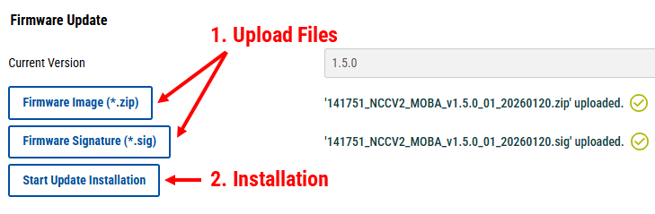
The update process runs automatically. If the installation is successful, the device will reboot up to two times to complete the update. If an error occurs, an alarm is raised, and the device continues operating with the currently installed firmware version.
Warning
During a firmware update, do not reboot or cut power to the device.
Note
The device verifies the integrity of the firmware update. Installation will fail if the firmware image has been modified. For instructions on manual verification, see Security FAQ.
Note
For security reasons, installation of older firmware versions is not permitted (anti-rollback protection). The device will reject such updates.
Rebooting#
Rebooting the device takes approximately one minute. A reboot can be used to restore the device to a clean operational state or to immediately apply certain changes that cannot easily be triggered externally. For example, rebooting forces the device to fully reinitialize its network interface, allowing it to immediately respond to changes in the network infrastructure (such as a modified IP address assignment from a DHCP server). Most configuration changes do not require a reboot to take effect.
Reboots are typically performed manually (for example, during troubleshooting) or automatically as part of another process (such as a firmware update).
Alarm Testing#
The Dummy Error function provides a simple way to test supervision and alarm handling settings. This alarm can be manually enabled or disabled from the Maintenance page.
When enabled, the device treats the dummy error like a real fault condition. It is logged accordingly and reported through all configured notification mechanisms (for example, syslog).
Note
The dummy error is a configuration parameter. It persists across reboots and is included in configuration backups. Once enabled, it remains active until it is manually disabled.
Factory Reset#
A factory reset restores the device to its initial state and permanently deletes all user data, including configuration settings and log files.
A factory reset can be initiated in one of the following ways:
Digitally, by an authenticated admin user
Physically, using the reset button on the device
Factory resets via the physical reset button can be disabled using the Allow Unauthenticated Factory Reset option. In this context, unauthenticated means that anyone with physical access to the device can press the reset button and trigger a factory reset. For additional security considerations, refer to the Cyber Security chapter.
Note
Only disable the factory reset button after verifying that the admin login is functional and the password is securely stored (for example, in a password manager). If the reset button is disabled and the admin credentials are lost, the device cannot be accessed or recovered, and all stored information will remain permanently inaccessible.
SSL Certificates#
When accessing the device for the first time, your browser may display a security warning because the default TLS certificate is not trusted. To remove this warning, you can upload a custom TLS certificate issued by a trusted authority within your organization.
Certificates can be uploaded from the Maintenance page. You must provide:
The TLS certificate (in PEM format)
The corresponding private key (in PEM format)
You may either paste the contents directly into the provided text fields or upload the files from your computer. After a successful upload, the device will use the new certificate for all subsequent HTTPS connections.
For optimal performance, the use of Elliptic Curve Digital Signature Algorithm (ECDSA) certificates is recommended. ECDSA certificates provide comparable security to RSA certificates while requiring less computational overhead.
The device validates all uploaded certificates and will reject certificates that are malformed or that use unsupported cryptographic algorithms.
Backups#
Backups allow you to restore the device configuration at a later time. For security reasons, backup files are encrypted using a user-defined password. This password is required when restoring the backup.
A backup includes:
Device configuration
Enabled user accounts and their credentials
A backup does not include log files or other runtime-generated data.
Create a Backup
Click Create Backup.
Enter an encryption password.
The encrypted backup file is automatically downloaded to your computer.
Restore from a Backup
Upload the backup file.
Click Restore From Backup.
Enter the correct decryption password.
The device restores the configuration and reboots automatically.
Support Package#
A support package contains diagnostic and troubleshooting information that can be shared with customer support. The package is encrypted and can only be accessed using the specified encryption password.
Create a Support Package
Click Create Support Package.
Enter an encryption password.
The encrypted package is automatically created and downloaded to your computer.
Provide the package to customer support together with the decryption password.
The support package may include:
Device configuration
Log files
Self-test results
Network and routing information
Salted password hashes of all enabled user accounts
The support package does not include highly sensitive information such as TLS/SSL private keys.